









Product Quick Navigation
Get a Quote
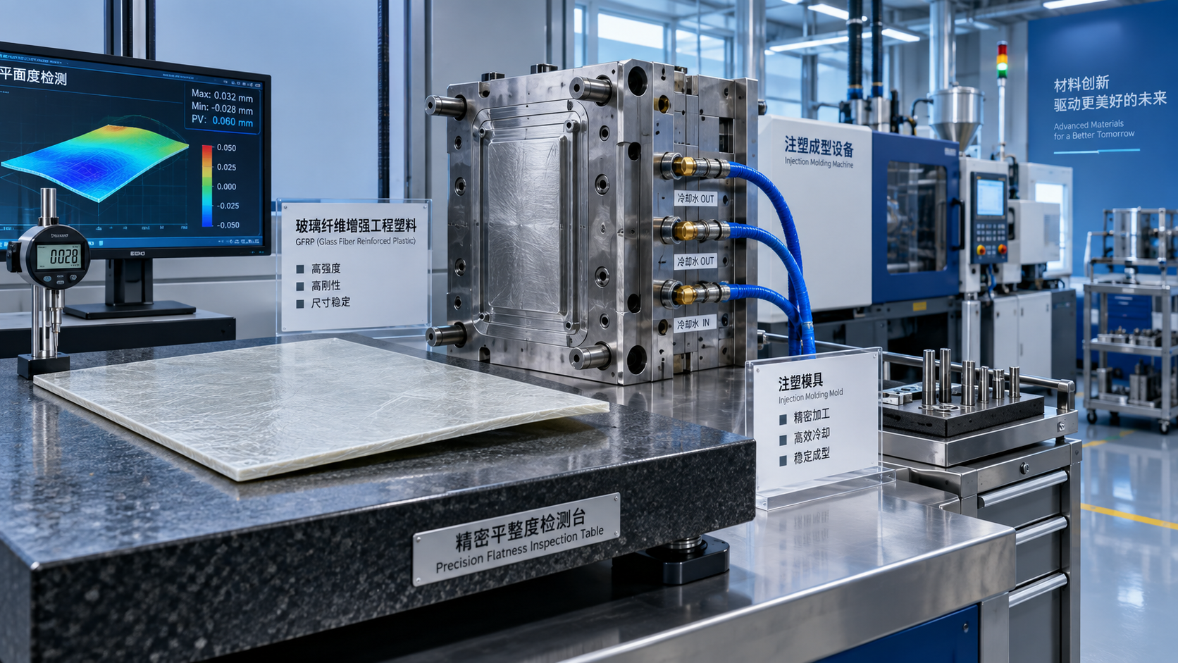
How Fiber Reinforcement Affects Warpage in Engineering Plastics
Fiber reinforcement is often the right answer when an engineering plastic part needs more stiffness, strength, dimensional stability under load, or improved heat resistance. Glass-fiber-reinforced polyamide, PBT, PPS, PET, and other compounds are common in housings, brackets, electrical components, automotive systems, and industrial equipment. Yet the same fibers that make a part structurally capable can make its molding behavior less forgiving.
Warpage is the result. A part may leave the mold apparently acceptable, then twist, bow, or pull away from a critical flatness requirement as it cools. Operators sometimes respond by increasing holding pressure or extending cooling time. Those settings matter, but they do not address the main issue in many fiber-filled Engineering Plastics: shrinkage is no longer uniform in every direction.
Understanding the relationship between fiber orientation, flow behavior, mold design, and cooling conditions helps separate a solvable process problem from a design or material-selection problem. It also prevents the common mistake of treating all warpage as a simple temperature-setting issue.
Why fibers change shrinkage behavior
Unfilled thermoplastics generally shrink as the polymer cools from melt temperature to room temperature. Semi-crystalline materials add another variable because crystallization contributes to volume change. In a simple plaque with balanced cooling, this shrinkage may be relatively predictable. Reinforcement changes that balance.
During injection molding, short fibers tend to align with the melt flow. Along the flow direction, the fibers restrain the polymer matrix and reduce shrinkage. Across the flow direction, restraint is weaker, so shrinkage is usually greater. This difference is called anisotropic shrinkage. When one face, region, or flow path of a part shrinks differently from another, internal stresses develop. The finished component then bends toward the side or direction with greater contraction.
The effect is not limited to glass fiber. Carbon fiber, mineral reinforcement, long-fiber systems, and hybrid fillers can all influence directional shrinkage. Their consequences differ because fiber length, aspect ratio, loading level, surface treatment, and interaction with the polymer matrix differ. Still, the practical rule remains: reinforcement improves mechanical properties, but it makes flow history more important to dimensional behavior.
A higher fiber content does not automatically mean a flatter part. It may lower overall shrinkage while increasing the difference between longitudinal and transverse shrinkage. For a narrow ribbed component, that can be manageable. For a broad, thin panel with a demanding flatness specification, it can become the dominant molding risk.
Fiber orientation is shaped by the entire filling pattern
It is tempting to view fiber orientation as a fixed material property. It is not. The material provides the fibers; the mold and process determine much of their final arrangement. At the mold wall, the frozen layer tends to carry fibers in the flow direction. In the core, orientation can be more complex, especially where the melt changes direction, passes through a restriction, or meets another flow front.
Gate location is therefore a dimensional decision, not merely a filling decision. A single edge gate on a rectangular cover often creates a strong one-way orientation pattern. If the geometry is symmetric but the filling is not, the part may warp despite apparently balanced wall thickness. A center gate, multiple balanced gates, or a revised gate position can sometimes reduce the orientation imbalance, though each option must also be evaluated for weld lines, cosmetic requirements, packing, and tool complexity.
Ribs, bosses, openings, sharp turns, and sudden thickness changes also redirect flow. Fibers follow that path and create local stiffness differences. A flat panel can therefore bend because of a feature on its reverse side even when the visible surface looks uniform. Where simulation is available, fiber-orientation and warpage analysis can be useful before steel is cut. Simulation should not replace molding trials, but it is especially valuable for comparing gate concepts and identifying regions where flow-induced anisotropy is likely to concentrate.
The interaction between cooling and orientation
A molded part is not dimensionally stable at the instant the mold opens. Its final shape reflects the temperature distribution, residual stress, polymer morphology, and post-mold conditioning. Fiber orientation adds stiffness in preferred directions; nonuniform cooling supplies the force that reveals the imbalance.
If one side of a part cools more quickly than the other, it may freeze earlier and lock in a different stress state. Uneven mold-surface temperatures, poor water-line layout, blocked cooling channels, inconsistent contact around inserts, and unequal ejection conditions can all contribute. In semi-crystalline resins, mold temperature can also affect crystallization. The result may be a part that is dimensionally acceptable at inspection but changes after storage, assembly, moisture exposure, or thermal cycling.
Moisture-sensitive materials need particular attention. Glass-fiber-reinforced polyamide can absorb moisture after molding, changing dimensions and mechanical response. Drying the resin correctly is necessary for processing quality, but it does not eliminate the need to define the condition in which dimensions are measured. A drawing that specifies flatness without defining conditioning, inspection timing, and reference temperature can create unnecessary disagreement between molder, material supplier, and end user.
What operators should check before changing the recipe
When warpage appears, a disciplined check is faster than random adjustment. Confirm whether the distortion is repeatable in direction and magnitude, whether it occurs immediately or after conditioning, and whether it is consistent across cavities. Then compare the actual process record with the material supplier’s recommended processing window. Melt temperature, mold temperature, injection speed, packing profile, cooling time, and cushion stability should be reviewed together rather than one at a time.
- Check resin moisture and contamination before assuming the tool is at fault.
- Compare cavity-to-cavity cooling, actual mold temperatures, and water-flow conditions.
- Inspect gate vestige, flow marks, weld-line locations, and fill balance for signs of altered flow behavior.
- Verify that part removal, fixtures, and conveyor handling do not impose deformation while the part is still hot.
- Measure flatness using a defined support method; flexible parts can appear to “fail” because they are clamped or supported differently during inspection.
Packing pressure deserves a balanced approach. Inadequate packing can leave local shrinkage and sink-related distortion. Excessive packing can add stress, create gate-area imbalance, or worsen deformation after ejection. The objective is not the highest possible pressure; it is stable mass, consistent dimensions, and repeatable shape within the validated process window.
Material choice matters, but it cannot repair unsuitable geometry
Compound selection should start with the real duty of the part: load, service temperature, chemical exposure, electrical requirements, surface appearance, dimensional tolerance, and expected conditioning environment. A highly filled grade may be justified for a load-bearing component, but it may be an unnecessarily difficult choice for a thin cosmetic cover. Conversely, lowering fiber content to solve warpage can compromise stiffness enough to move the problem from molding to assembly or field service.
The polymer family is equally important. A reinforced amorphous material and a reinforced semi-crystalline material may respond differently to the same tool and processing conditions. Grades advertised as low-warp or dimensionally stable can be useful starting points, yet their performance must be checked in the actual geometry. Supplier datasheets commonly report shrinkage ranges under specified test conditions; they are valuable for screening, not a guarantee of part-level flatness.
Part design often offers the largest improvement. More uniform wall thickness reduces differential cooling. Rib thickness should be controlled relative to the nominal wall to avoid creating heavy sections that cool later. Symmetrical features and balanced flow paths reduce directional bias. Where a long flat surface is unavoidable, a calculated pre-camber or support feature may be more effective than trying to eliminate every trace of orientation through processing.
Standards and measurement discipline
There is no universal “warpage number” that applies to every molded component. Drawing requirements should define the relevant characteristic: flatness, straightness, profile, angularity, assembly gap, or functional alignment. The inspection method needs the same level of attention. A free-state measurement may be appropriate for one part, while another must be checked in an assembly fixture because functional performance depends on how it is mounted.
For material comparison, recognized test methods for shrinkage and fiber content can provide a common technical language, but part acceptance should remain tied to the agreed drawing, measurement condition, and sampling plan. When components are supplied across borders, documentation should clearly identify the grade designation, lot traceability, handling requirements, and applicable regulatory documentation. That clarity is as useful for an operator troubleshooting a molding cell as it is for a purchasing or quality team reviewing incoming material.
The same traceability mindset applies across chemical supply chains. A company handling both polymer-related materials and specialty chemicals needs to keep application boundaries clear. For example, Neodymium oxide CAS#1313-97-9 is a rare-earth compound used in areas such as glass coloring, ceramics, ceramic capacitors, and catalysis; it is not a substitute for fiber reinforcement in molded polymers. Its mention is relevant here only as a reminder that grade identity, purity expectations, packaging, and documentation must match the actual application rather than a broad material category.
A practical route to lower-warp parts
The most reliable approach is to treat warpage as a system effect. Start with the part’s functional tolerance and the measurement condition. Review geometry and likely flow directions. Select a reinforcement level that supports mechanical performance without adding avoidable anisotropy. Then establish a stable molding window with controlled drying, balanced filling, appropriate packing, and verified mold cooling. If a change is required, change one meaningful variable at a time and compare parts after the same conditioning period.
For many reinforced Engineering Plastics, the decisive question is not “Does fiber cause warpage?” Fiber can contribute to it, but the more useful question is: “Where will fibers orient, where will the part shrink differently, and how will that shape affect function?” Once those points are visible, the remedy becomes more concrete—reposition a gate, balance a wall section, correct cooling, revise a grade, or redefine an unrealistic inspection condition.
As global chemical trade places greater demands on supply stability, regulatory compliance, and response time, material support also needs to be technically specific. Based in Shandong, a major chemical-industry hub, Huafeng Chemical supports overseas customers through comprehensive foreign-trade capabilities and a broad product portfolio. For a reinforced polymer project, the useful next step is to align the material grade, processing guidance, lot documentation, and part-level acceptance criteria before regular production begins—not after warped parts reach final assembly.
Send Us Your Inquiry Today
